When waste is turned into a raw material
In the past, two ash fractions, from the process of paper sludge (fine clay) combustion were transferred by means of directly downstream mechanical transport from the boiler and via exhaust air filters to two tandem-arranged pneumatic conveyors and then conveyed to a 600 m³ silo. A total mass flow of around 2500 kg/h waste is handled in this process. The ash fractions differ substantially in their particle size continuum and exhibit different product properties especially with regard to pneumatic conveying and storage along with discharge from the existing silo.
Objective of the redesign of the existing plant is, with consideration of energy aspects, to store the boiler ash in the existing 600 m³ silo and the filter ash in a 400 m³ silo to be erected and to enable with two separate lorry loading operations the separation of the ash as described in the introduction and the logistic handling of the two ash fractions. In addition, the more difficult discharge of the very much finer filter ash fraction from the new silo has to be considered. Moreover, cooling of the filter ash together with suitable pneumatic conveying system and proper activation of the product flow out of the 400 m³ silo must be integrated.
After consideration of the space available within the existing plant for integration of the new components as well as the possibility for the short-term intermediate storage of the two product streams on site, the following system was installed.
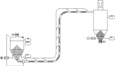
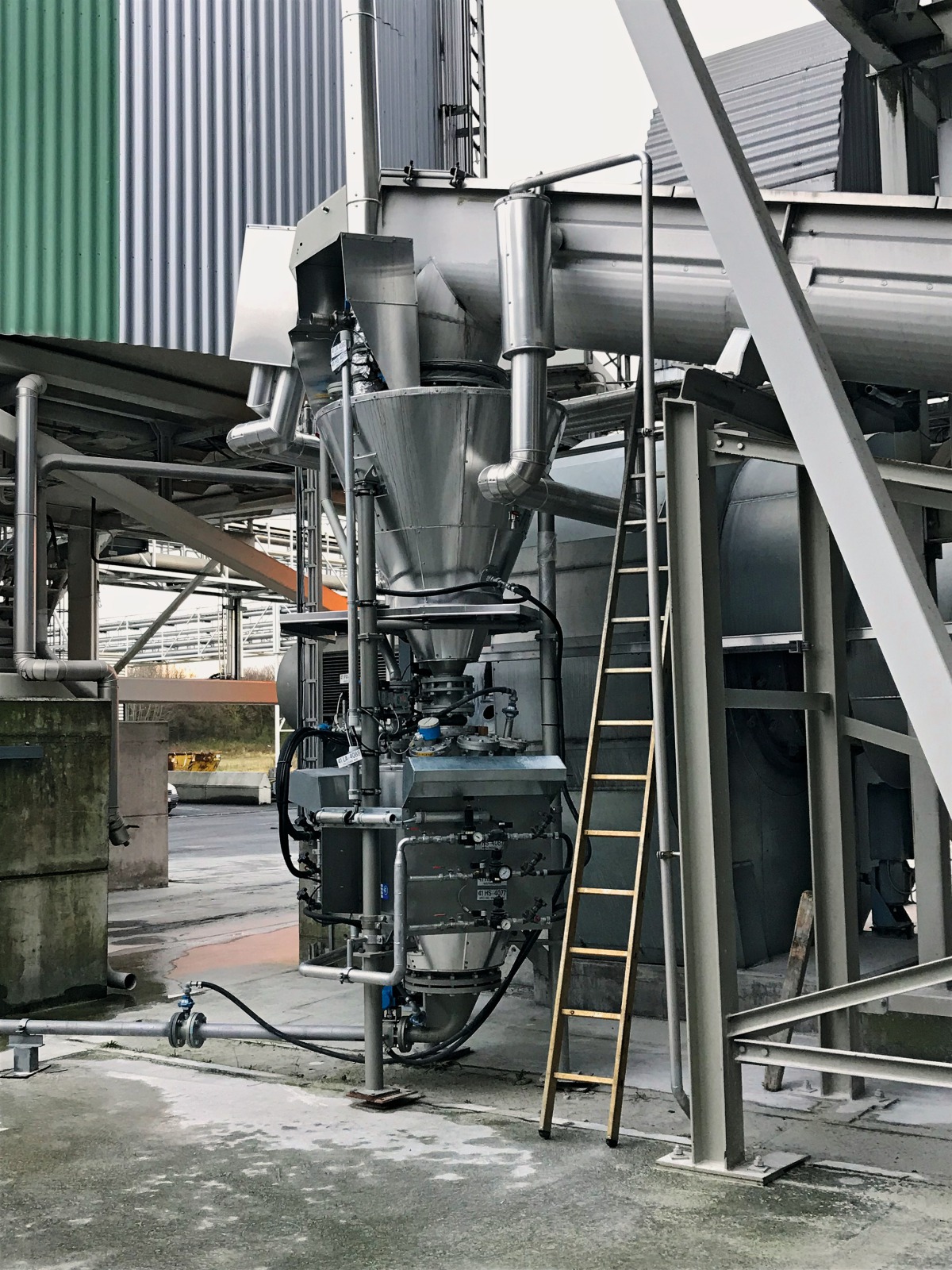
Ash transport downstream of the cooling screw conveyor to the ash silos
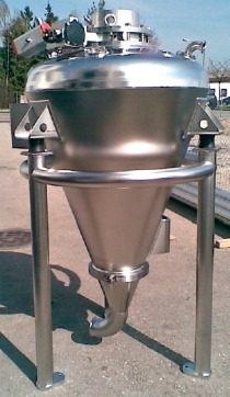
The conveying route activated in the process control system for each ash fraction reaches the feed hopper of the solids pneumatic conveyor via an installed cooling screw conveyor. The feed hopper is used for short-term intermediate storage of the continuous ash flow during the conveying cycle of the solids pneumatic conveyor. With a gross volume of 450 dm³, the feed hopper is optimally designed and equipped for reliable operation with solids fluidizing pads for product flow activation as well as a vent pipe to the ash filter.
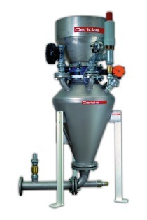
With its extremely rugged design, the downstream solids conveyor from the PHP-Heavy series ensures reliable conveying of the up to 120 °C-hot and abrasive ashes. Here the use of a solids pivoting shutter as conveyor inlet lock ensures the filling of the sender conveyor without the product stream being hindered and, additionally with the help of an inflatable seal, the best protection against abrasion and leakages. The solids conveyor is deaired by means of a balance air pipe to the feed hopper. The delivery capacity of the sender tank with 300 dm³ filling volume is around 5000 kg/h at around 27 conveying cycles per hour.
For the conveyor pipeline, in view of the course of the line and minimizing the buffer time in the feed hopper, a nominal width of 100 mm has been selected. The pipeline is engineered in a thick-walled design, and it is supplied and fully assembled including pipeline mounts. Pipeline diversions are realized with solids CEB pipe bends and solids DFR end-pieces made of abrasion-resistant cast steel. By means of an automatic solids two-way diverter, the conveying route to the designated silo is selected. The conveying medium and product are separated in the silo with the help of silo top filters with a residual dust content of 5 mg/m³ exhaust air.
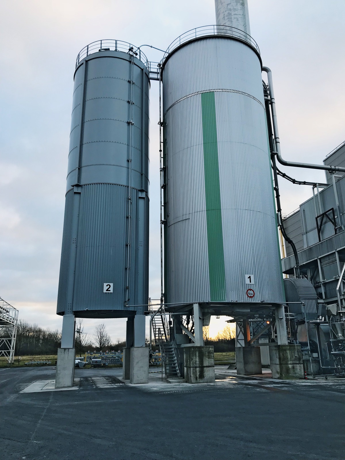
Silo with silo discharge and lorry filling
The new 400 m³ steel silo is assembled in bolted design with a diameter of 4600 mm and closed skirt support directly on site. At the four supports of the associated steel structure with bottom clearance, gravimetric level detection based on strain gauges is integrated. In addition, the silo has all internal fittings for reliable operation.
The reliable discharge of the sometimes very fine ash (d50 approx. 25 µm) in the “mass flow” discharge regime is realized primarily with a solids vibrating floor discharger with electromotive drive. To ensure further material flow, eight solids ADS aeration panels together with their pneumatic installations are installed at the silo cone. They serve as secondary product flow activation in case after relatively long stoppages, product bridges should form in the silo cone.
The solids gate valve with a nominal width of 300 mm mounted directly at the discharge of the solids vibration discharger enables safe inspection of the lorry loading below. Connected to this there is a compensator for decoupling the vibrations of the solids vibration discharger from the solids ZRS rotary valve.
For a metering of the ash from the vibration discharger to the loading equipment, a solids ZRSR2533B01 rotary valve with a delivery capacity up to 120 m³/h is installed. The rotary valve is mounted on a separate steel structure, which additionally bears the load of the downstream solids lorry loading.
For the dust-free transfer of the product stream into a silo truck, a solids TLC3 filling unit with lifted and lowered chute and direct dedusting with an integrated system filter is installed. An inflatable seal at the “loading chute – inlet” interface ensures dust-free filling of the lorry trailer.
For control of the plant, a complete switch cabinet with all control and load modules is supplied. It is activated automatically via the customer’s process control system. For semi-automatic and manual operation, the main switch cabinet comes with a 15” touch-panel with all plant visualizations and access to all readable system and operating parameters.
Conclusion
Thanks to meticulous collection of all product and operating data, with determination of selected individual parameters in solids own materials laboratory and the associated testing centre, the realization of this project could be based on a reliable design concept. The more than sufficient material data collected form the basis for reliable design of all equipment installed and, together with the decades of experience, lead to reliable engineering for the entire system.
Operation of the plant presented here enables the customer to separately load two previously inseparable ash fractions, the energy efficiency and operational reliability of the system contributing to high customer satisfaction.
Autor/Author:
//www.solids.de" target="_blank" >www.solids.de:www.solids.de