Radiometric Measurements
Radiometric measurements for industrial processes have been around for several decades. They are an important component in the performance of critical level, density and flow measurements. Nuclear measurement gauges work where conventional measuring technology fails. They offer outstanding measurement results under extreme conditions.
High temperatures, pressures and other difficult ambient and process conditions are no problem for radiometric measurements. Typical measurement tasks are non-contact level and density measurements in various vessels, bunkers and piping systems, interface measurements in oil separators and moisture measurement. They can also be used as non-contact limit switches.
What is a radiometric measurement?
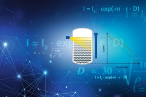
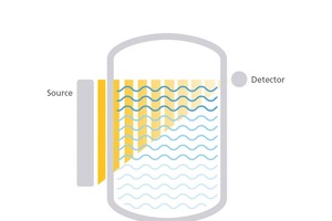
Nuclear measurement gauges operate on a simple yet sophisticated concept – the principle of attenuation. A typical radiometric measurement consists of
a source that emits γ-radiation, produced from a nuclear radioisotope
a vessel or container with process material under investigation
a detector capable of detecting γ-radiation
If there is no or little material in the pathway of the radiation beam, the radiation intensity will remain strong. If there is something in the pathway of the beam, its strength will be attenuated. The amount of radiation detected by the detector can be used to calculate the desired process value. This principle applies to virtually any nuclear measurement. Nuclear measurement technology is highly reproducible. Using the laws of physics and statistics, as well as sophisticated software, the success of any nuclear-based measurement is almost granted. However, correct and exact application information is imperative for the design of an accurate and reproducible measurement. Considering the benefits of a totally non-contacting and non-intrusive technology, nuclear measurement technology becomes the number one method and only choice for the most difficult and challenging process measurement applications. Every measurement involves and comprises errors and radiometric measurements are no exception. In this document we will elaborate on the nature and causes for such deviations and how they can be suppressed by applying best practices and good workmanship.
Radiation sources
There are many known natural and artificial radioactive isotopes, not all of them are used for radiometric measurement. In industrial applications just a few nuclides are actually used for measurement purposes. The radioactive isotope is usually placed in a rugged, steel-jacketed, lead housing for maximum safety. The housing shields the radiation, emitted from a radioactive isotope, except in the direction where it is supposed to travel. Using a small collimated aperture in the shield, the beam can be projected at various angles into the pipe or vessel. This warrantees a high quality of measurement with minimal exposure of personnel to radiation. Basically, the ALARA (As Low As Reasonably Achievable) principle for maximum work safety applies on everything that has to do with nuclear isotopes.
Radioactivity
The most commonly applied isotopes are Cesium-137 and Cobalt-60. Sometimes Americium-241 is used for certain applications. They differentiate from each other in half-life time, but also by the emitted gamma energy. It is very easy to confuse the meaning of “activity” and the “energy” of the emitted radiation from a source:
Activity describes the average number of the isotope’s nuclear decays that result in an emitted gamma quantum. Or in other words: the amount of radioactive material.
Each gamma quantum has a specific energy. The energy distribution of emitted gamma quant is characteristic for each isotope. The gamma energy is directly linked to the ability of the radiation to penetrate through materials (media, vessel, etc.).
It is important to understand that the number of emitted gamma quanta – and hence the activity – has nothing to do with their energy. This is similar to the colour of light which is not linked to its brightness. Also, the half-life time should not be confused with the lifetime of a source! While the half-life time of an isotope is an unchangeable physical property of the isotope and refers to the time in which the activity of a material reduces to half, radiometric sources are typically designed for a lifetime of 10 to 15 years, independent of the isotope being used. The selection for a specific measurement task is based on the media to be measured, but also the setup (i.e. point or rod source) and onsite constructional specifics. The decay of any isotope is following the stochastic theory and therefore can be analysed with the use of statistical methods.
Point sources
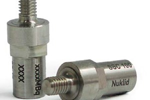
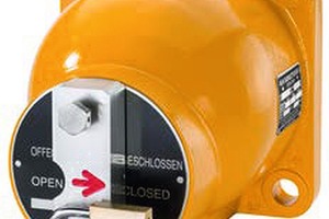
Point sources are widely used in literally any measurement task, whether it is density, level or the use as limit switch. They usually comprise an inner source capsule, which securely encapsulates the radioactive material and a shield with a shutter mechanism to block the radiation in a controlled way.
Rod sources
A rod source is a device where the active area is continuously distributed over the complete measuring range. This can be done by winding an activated Cobalt wire (Co-60) on a carrier. One of the benefits of a rod source is, that a “perfectly” linear calibration of the detected signal (count rate vs. level %) can be achieved, meaning the percent change of the count rate is direct related to the percent change of the process value.
Detectors
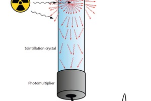
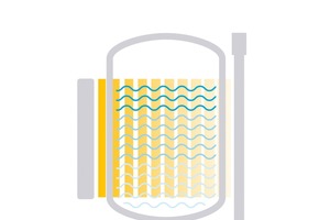
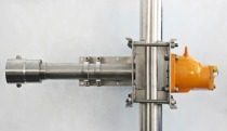
The radiation detector contains a crystal made from a special polymer material or an inorganic crystal, like doped sodium iodide – the so-called scintillator. The scintillator converts the incoming gamma into flashes of visible light. The crystal is optically coupled to a photo multiplier, which converts light into electrical pulses. While the vacuum photomultiplier has been used successfully for decades, nowadays also silicon photomultipliers (SiPM) are available and are becoming more and more established in industrial detectors. Adjacent figure shows schematically how a detector works. When the emitted gamma quants hit the crystal, after having passed through the walls of the vessel, pipe and the measured product itself, each gamma photon in the beam might generate a light flash, resulting in thousands of subsequent light pulses that are recorded by the photomultiplier tube. Each light pulse is converted into electrical pulses by the photomultiplier.
After digitizing of the signal, these pulses are counted to determine a so-called count rate, which is typically expressed as counts per second (cps) or frequency (Hz). The intelligence that distinguishes between various measuring tasks (i.e. level or density) is implemented in the transmitter or control unit. The count rate is used to compute a process related signal which can be used for a display, an analog current output or bus connections into a DCS or PLC. The detector measures any γ-radiation arriving in the scintillator, without distinction of “useful count rate” deriving from the source or natural background radiation from the environment. We will learn later how interference radiation coming from weld inspection, and changes in natural background radiation, etc. can be handled.
Point detectors
Detectors with a small scintillator are called point detectors. They often employ a small cylinder as scintillator, e.g. 50 mm diameter and 50 mm in height. They are typically used for density applications but also for level switch or continuous level measurements. Depending on the measurement task, other scintillator sizes may be used. Due to the small sensitive volume of a point detector it is not greatly affected from background radiation. Additionally, point detectors can be easily equipped with a lead collimator to further suppress sensitivity to background radiation.
Rod detectors
In some cases, it is beneficial to have the scintillator covering a longer range, this is called a rod detector. Typically, in level measurements either source or detector span over the whole measuring range. Their length can be up to 8 m. The main benefit of a rod detector is its lower cost compared to a rod source. Albeit, the rod source would be the technologically superior system. The gamma radiation which a rod detector is able to detect, is influenced by the geometry of the radiation array. However, as rod detectors are typically not shielded (and a shield would diminish the cost advantage) they are much more sensitive for changes in natural background radiation making this effect dominant to most other errors. Particularly, taking into mind that fluctuations of ±15 % i.e. through accumulation of Radon-222 and its decay products, e.g. after rain, are possible, which we will demonstrate later on.
Types of errors
Below different types of errors that occur in a radiometric measurement are elucidated. Clearly, everybody will immediately think of the statistical error, but we will show that there are other influences that create errors as well. Measurement errors can be classified into systematic errors and statistical (random) errors. A proper measurement setup delivers a good result with an appropriate accuracy and reproducibility. Often, by all means within acceptable tolerances, this is more important than the absolute accuracy of the value.
With this relation of accuracy and repeatability in mind, this article wants to talk about the special field of radiometric measurement and give an overview about:
Different types of errors. Usually people think more of statistical errors due to the nature of the decay of the radionuclide
Different types of measurement gauge
How different error types dominate in different applications
Relation between systems sensitivity of a good measurement and the Signal to Noise Ratio
Impact of the selection of the radiation source
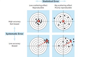
For clarification we will introduce some definitions and statistical terms. For that we use a target circle, with the center as the correct value. Every “shot on target” stands for a measurement result.
Statistical errors
Random errors are caused by inherently unpredictable fluctuations in the readings of a measurement apparatus or in the experimenter’s interpretation of the instrumental reading and are always present in any measurement. Random errors show up as different results for ostensibly the same repeated measurement. Such randomly occurring errors are called statistical errors and typically follow the Gaussian Normal Distribution and therefore can be handled with statistic methodologies.
Systematic errors
Systematic errors do not occur randomly, and under constant parameters, have a reproducible pattern. In a proper set-up, systematic errors are predictable and typically constant or proportional to the true value. For radiometric gauges amongst others, there are the following main systematic errors to be taken into consideration:
Sensitivity changes caused by temperature variations or detector components
Count rate variations due to changes in strength of natural background radiation (e.g. Radon)
Unpredictable noise through weld inspections or other interferences
Incorrect calibration
Temperature and aging effects
At least the first two systematic errors can be reduced by applying top notch compensation methods. Sophisticated algorithms and methods independently measuring the sensitivity of a detector by comparing the signal to a known reference can be used to compensate for these effects. Such an automatic gain control or high voltage control should be included into the measurement system. For example, the algorithms used by Berthold Technologies rely on a spectral analysis of either the radiation received from the primary radioisotope used, or – even more sophisticated – cosmic radiation to suppress these errors to not more than 0.1 % of the detected count rate over a temperature range from -60 °C to +70 °C and over a time period of more than 10 years.
Natural background radiation
We are always exposed to some naturally occurring radiation, mainly caused by cosmic or terrestrial radiation. This is called “natural background”. Changes in natural background radiation are much more difficult to compensate for. Before going into details of error suppression let’s have a look at the effect first. Background radiation is mainly caused by cosmic or terrestrial radiation. While the effect from cosmic radiation is very constant, the terrestrial background radiation can vary much depending on the geographic location. Different geological rock formations carry different amounts of naturally occurring radioisotopes, causing differences in the amount of terrestrial background radiation.
As one of the natural radio-isotopes, the noble gas Radon-222 (Rn-222) and its decay products, play a major role in the strength of the background radiation. Rn-222 is produced in rock formations and due to the physical properties of a gas reaches the earth’s atmosphere causing a measurable amount of radioactivity in the air, right above ground. Rain can also cause a temporarily increase of Radon decay product’s concentration on the ground and therefore cause an temporary higher background radiation. These changes in background radiation have a higher impact on rod detectors than on point detectors. This is due to the fact that point detectors are often installed with a collimator to suppress background radiation, whereas rod detectors are usually unshielded and have a significant higher scintillator volume. Hence, the signal to background ratio is typically much higher for point detectors than for rod detectors.
Interference radiation
Another unpredictable cause of interferences are ongoing weld inspections in the plant or complex. Typically, gamma sources (e.g. Iridium-192) are used and can cause a significant increase of background radiation. This causes the measured signal to change quickly and drastically, yielding to false readings of the process values. In case the radiation detector is not well-engineered, the signal may be disrupted much longer than the actual disturbance is present and may even cause permanent damage to the detector’s components. Devices equipped with Berthold’s X-Ray Interference Protection (XIP) feature detect interference radiation and freeze the measurement signal during the disturbance. Even more sophisticated is the RID feature (Radiation Interference Discrimination), which is based on a complex algorithm that allows to distinguish between interferences and real count rate emitted from a Cobalt-60 source of the nuclear gauge.
Calibration
Nuclear gauges work on the principal of attenuation. Basically, every matter interacts with γ-radiation and has an attenuating effect. Under process control perspective, this is not only the media to be measured, it is also the steel walls of the vessel, any inside construction, insulation, framework, etc. For example, a typical Delayed Coking Unit in a refinery is made of steel with a 20-50 mm wall thickness and has a diameter of 5-9 m, all packed in insulation. Thus, it is obvious that a level system needs to be calibrated onsite to reflect the non-process related attenuation. Hence, a factory calibration is not feasible. Also, density measurements have to be calibrated onsite with at least one reference point of known density.
Typically, the system is calibrated in known process conditions, e.g. a full and empty vessel in case of a continuous level measurement or at least one known density of the fluid in the pipeline for a density system. As important as a proper calibration is, so much can go wrong during this procedure.
Typical sources for errors are:
Calibration under the wrong conditions. Calibration should be performed as closely to process conditions as possible. Differing temperature, gas density, running agitators, spray nozzles, etc. might affect the attenuation and if these conditions prevail during calibration and not during the process, a systematic error is created.
Using false reference, e.g. calibrating a system to empty (0 % fill level), while there is still an amount of product in the vessel.
In density measurements, samples to determine the process value in the calibration table, which are not representative of the real condition.
Not enough time to acquire calibration count rates – see again the statistical error references in this abstract.
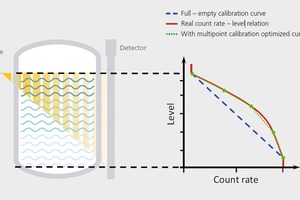
Even when the above sources of errors are well taken care of, there is another systematic error. In cases were a rod detector together with a point source is used,the correlation between count rate and filling level is not linear (longer radiation path and larger effective wall thicknesses at the lower end of the measurement range). Figure “Calibration curve” illustrates this effect. In case the measurement device now uses a straight line (blue) as a calibration this will yield to systematically reduced accuracy of the system, yet maintaining full reproducibility. Or in other words, the system will always indicate the same level at the same process conditions but with a deviation from the real level (red). A multi-point calibration could be used to linearize the curve, reducing the systematic error and therefore improve accuracy of the measurement (green). Nevertheless, often the reduced accuracy due to the non-exact linearity of the measurement is negligible and the high reproducibility of the measurement is key.
Other process and application related errors
Besides the above mentioned unavoidable, but with best practices and good workmanship manageable, systematic errors, there are several process and application related error sources. They are often underestimated and not taken into consideration; however, they can have a significant negative effect on the accuracy of your measurement. Obviously, these sources of errors have to be taken care of by the enduser of radiometric measurements and cannot be reduced by good workmanship of the measurement devices itself. Following is a list of possible sources for process and application related errors but reality does not limit the list to the below mentioned examples:
Media deposits on structural part
Crosstalk
Hydrogen content
Formation of foam
Slugs, gas bubbles or blowholes
Source shield closed
With all of the above in mind, you realize that the quality of a radiometric measurement is more than just sensitivity of the radiometric detector and that it is also affected by a number of systematic errors. In fact, sensitivity has to be seen in context of the whole performance and functionality of the system. Without the right measures in place, more sensitivity also increases the measured background and does not necessarily improve the overall system performance. Like for our TV example, if just the signal is amplified, this includes the noise, hence it is not improving the overall quality of the system. Thus, the target should be to improve the signal to noise ratio, instead of purely focusing on the sensitivity.
Application types
Level switch
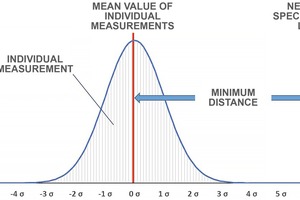
A level switch is a point-to-point measurement, utilizing a point source and a point detector. Systematic errors can be reduced very well, by applying good workmanship during installation and setup of the measurement. This includes establishing the system with properly calculated switching limits. The most important and dominant error of a nuclear limit switch, is the statistical error, which is handled by statistical methods, e.g. by setting an appropriate time constant and build a reasonable mean value. Designing the system with a high enough count rate and leaving a large enough sigma difference between empty and full counts, prevent from false switching. The Figure “Reliable switching limits” illustrates that for safe switching operations a difference of at least 6 σ is recommended. Count rates leaving the 6 σ band due to statistical variations occur in 0.0000 001 973 % of all measurements – only every 16 years when applying typical detector characteristics.
Density
Similar to the nuclear limit switch, density measurements are typically point-to-point measurements, with the same error modes. For density measurements it is important to carefully manage the potential causes for systematic errors. As already explained, sophisticated temperature and aging compensations preserve the high reproducibility of the measurement itself. Also, it is imperative to establish a proper calibration, where sample taking and laboratory measurements might affect the accuracy of the calibration value. In the measurement itself the statistical error is most dominant. In real life a density measurement has high demands on accuracy and reproducibility in a very limited calibration range. Typically, the count rate ratio at the highest and lowest measured density is low and therefore the acceptable statistical error is quite small, which prohibits the use of similar count rates to a limit switch. To handle the statistical error, it helps to have a high count-rate in combination with a long time constant.
Continuous level
While for nuclear limit switches and density measurements the point-to-point connection, utilizing point source and point detector is the industry standard, continuous level measurements usually utilize at least one rod type device. As indicated earlier, rod detectors are very vulnerable against background, and therefore the potential errors caused by background are by far dominating. The sensitivity of a radiometric measurement is not automatically an indicator for the quality of the measurement. It is obvious that background and its fluctuation play a major role and error caused by background can dominate the system. Typically, it is thought that cutting activity half is having the same effect than bisecting the sensitivity. Halving sensitivity of the detector does not change the systems overall error assuming that there is no other major source of noise like electronical noise, which can only be held up if the measurement device is developed and produced on a high standard. In fact, calculations illustrate, that the signal to noise ratio is the far better lever and this ratio is what we positively influence by managing background.
Summary
As we have elaborated in this abstract, there is no such thing like a 100 % accurate measurement and for a user there are many potential pitfalls. Some are specific to radiometric measurement and therefore need specific provisions, some can be handled by applying good workmanship and common technical sense. For any measurement it is important to use an adequate measurement tool and setup that fits the purpose, including providing the right level of accuracy.
For radiometric measurements accuracy heavily depend on the counts that are red and how they are interpreted. Obviously, sensitivity is a factor. It however is just part of the equation and it is a kind of precondition. A certain sensitivity is needed to reach a good measurement. But remember, a sensitive system reacts on every gamma radiation – what includes background. As rule of thumb it can be said that for point detector sensitivity is key. Background can be excluded very well (collimator) and therefore has a less impact. For rod detectors background becomes a dominating factor and sensitivity alone is not significant.
Thus, it is more important to have a holistic look on the system instead focusing purely on sensitivity. A sample calculation, show that halving the sensitivity has nearly no effect on the measurements accuracy. By making sure the measurement system is well designed to provide a good signal-to-noise ratio, we provide real benefit to the user. This is where the experts from Berthold together with their superior technology can help to generate real value for the customer.


