New potentials in the dynamic simulation of belt conveyors
 Quelle/Source: ESI ITI GmbH
 Quelle/Source: ESI ITI GmbH
 Quelle/Source: ESI ITI GmbH
 Quelle/Source: ESI ITI GmbH
 Quelle/Source: ESI ITI GmbH
 Quelle/Source: ESI ITI GmbH
 Quelle/Source: ESI ITI GmbH
 Quelle/Source: ESI ITI GmbH
 Quelle/Source: ESI ITI GmbH
 Quelle/Source: ESI ITI GmbH
 Quelle/Source: ESI ITI GmbH
 Quelle/Source: ESI ITI GmbH
 Quelle/Source: ESI ITI GmbH
 Quelle/Source: ESI ITI GmbH
 Quelle/Source: ESI ITI GmbH
 Quelle/Source: ESI ITI GmbH
 Quelle/Source: ESI ITI GmbH
 Quelle/Source: ESI ITI GmbH
 Quelle/Source: ESI ITI GmbH

Summary: In many industries, system simulation is now the standard tool for the development, design and analysis of all types of complex machinery and systems. A model for belt conveyors permits the investigation of a most diverse range of aspects. It can be used for analysis of issues in various disciplines, including, for example, mechanics and drive technology, also in thermodynamics, up to and including control systems. Such a model permits virtual commissioning and also the development of a Hybrid TwinTM – a virtual twin of the system based on simulation models and data.
1 The state-of-the-art in simulation
of dynamic processes in belt conveyors
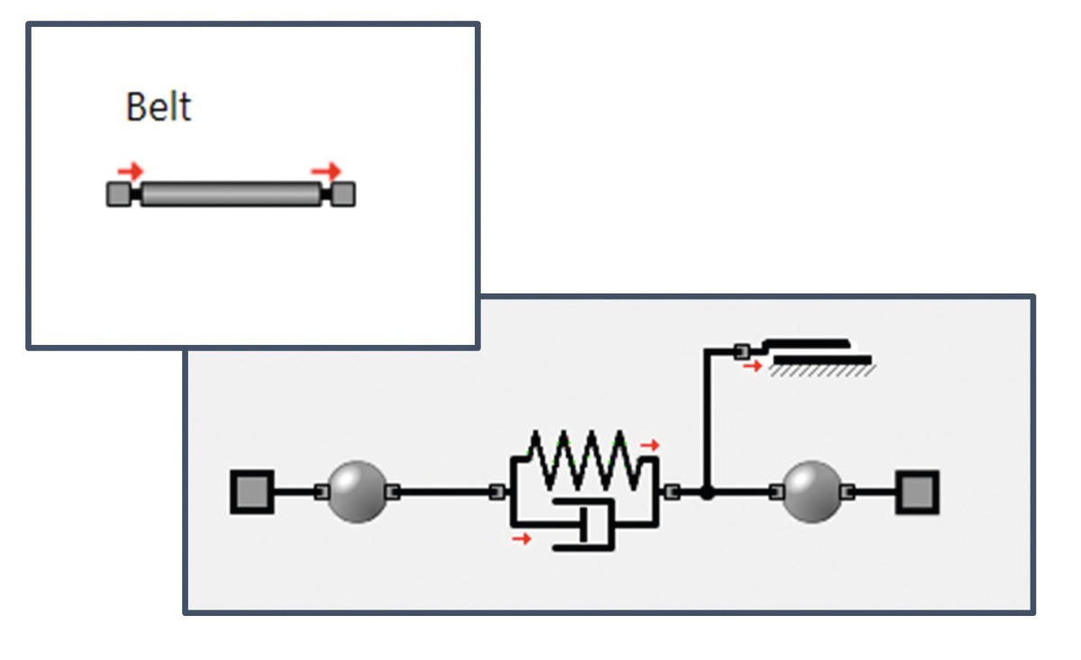
Dynamic dimensioning and design of belt conveyors are now well established on the conveying and handling systems market. Modelling of these systems has been based, since the first publication [2] in 1975 and up to today [3], on the breaking down of the belt into individual sections. These belt sections can be represented by mass-spring-damper elements (Fig. 1). The second important model element in the belt sections includes description of resistance forces. Dimensioning concepts from standards and specifications, such as DIN 22101 [1], for example, exist for this purpose. This standard determines total resistance to motion from the sum of the following individual resistances:
F = FH + FN + FSt + FS
in which FH is primary resistance, FN is secondary resistance, FSt is slope resistance and FS is special resistance. Attention is drawn to [1] and scientific works such as, for instance [3], for a detailed examination of this.
2 Efficient modelling –
The SimulationX Belt Conveyor Library
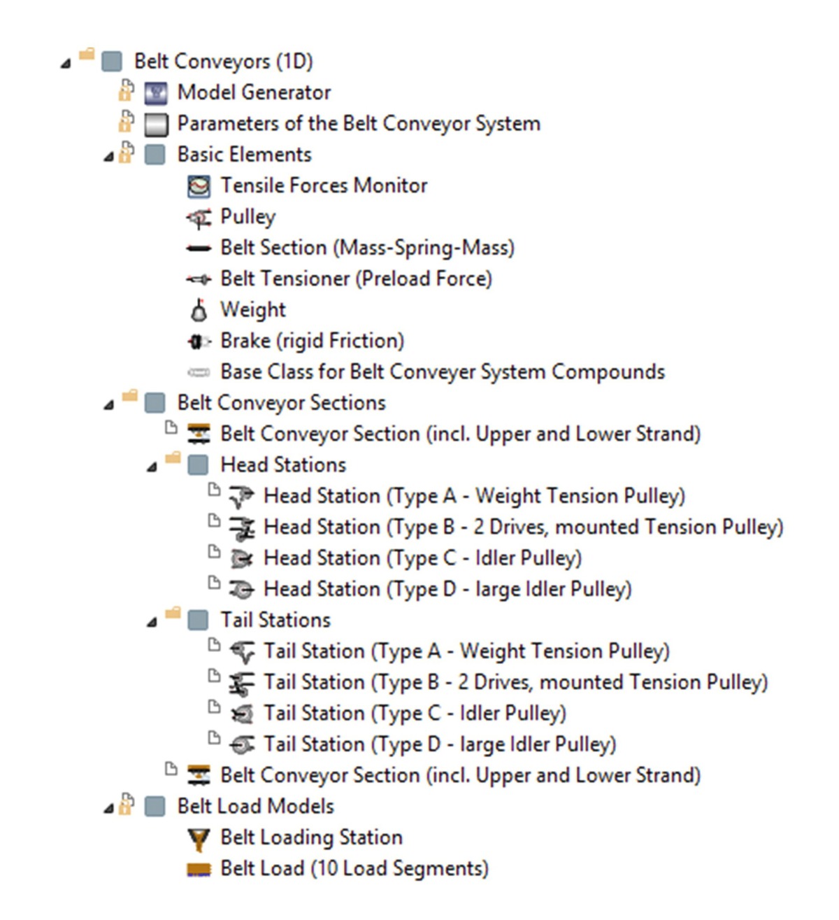
The SimulationX belt conveyor library provides the user with the fundamental model elements of components such as drive pulleys, tensioning systems and belt segments. Building on this, it provides models of complex stations, such as, for example, drive units and belt sections, inc. load tracking, which are among the most important model elements (Fig. 2).
2.1 The most important model elements
Belt conveyor section
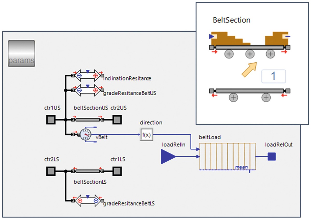
Fig. 3 shows the “BeltSection” element and its basic structure. The belt segments (beltSectionUS, beltSectionLS) include belt dynamics and description of the losses of the belt section in the top run and the return run. Load tracking (beltLoad) makes it possible to simulate changing load situations.
Head and tail stations
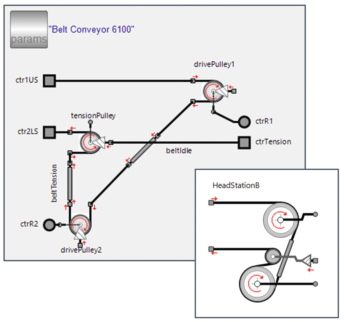
The belt conveyor library includes various types of drive stations. Fig. 4 shows the HeadStationB element by way of example. Its structure illustrates the arrangement of such a unit on the basis of the fundamental elements of pulley and belt segment. Further stations can be implemented in this way if needed.
2.2 The model generator
The mechanical models of belt conveyors differ essentially in the number of belt sections observed, the height profile and the drive station used at the head and/or tail of the belt conveyor.
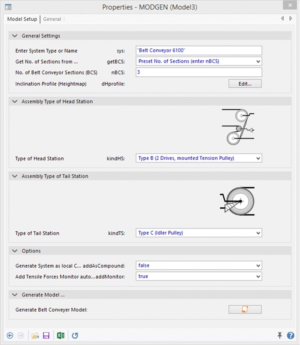
Conventional generation of such a model can take a considerable time. This input can be drastically reduced via the use of a model generator (Fig. 5). After entry of the height profile and selection of the drive stations, this generator automatically creates the conveyor model and refers all parameters of the model elements to the central parameter element. The model is ready for use once parametering has been completed.
2.3 Parameters
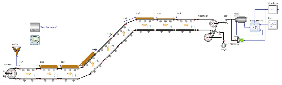
Fig. 6 shows a belt conveyor model by way of example. In addition to the belt conveyor elements, the model also includes elements from SimulationX libraries, which are defined by the respective analysis task and the degree of detailing necessary for this purpose. This make it possible, for example, to generate more complex models of the drive train and of the motor, and to test various control concepts. The model example includes a geared transmission system, a model motor and a speed controller. Various results are calculated during simulation, including, for example:
Effective pulling forces on every section and every pulley
Resistance forces and velocities of the belt sections
Speeds, drive torques, power and losses, slippage where appropriate
The plot of load
The results are available for further use after the simulation. The trend against time of various results can, in addition, be visually displayed during simulation, which contributes tangibly to the achievement of enhanced and also interdisciplinary comprehension of the system behaviour of the belt conveyor.
3 Examples of application
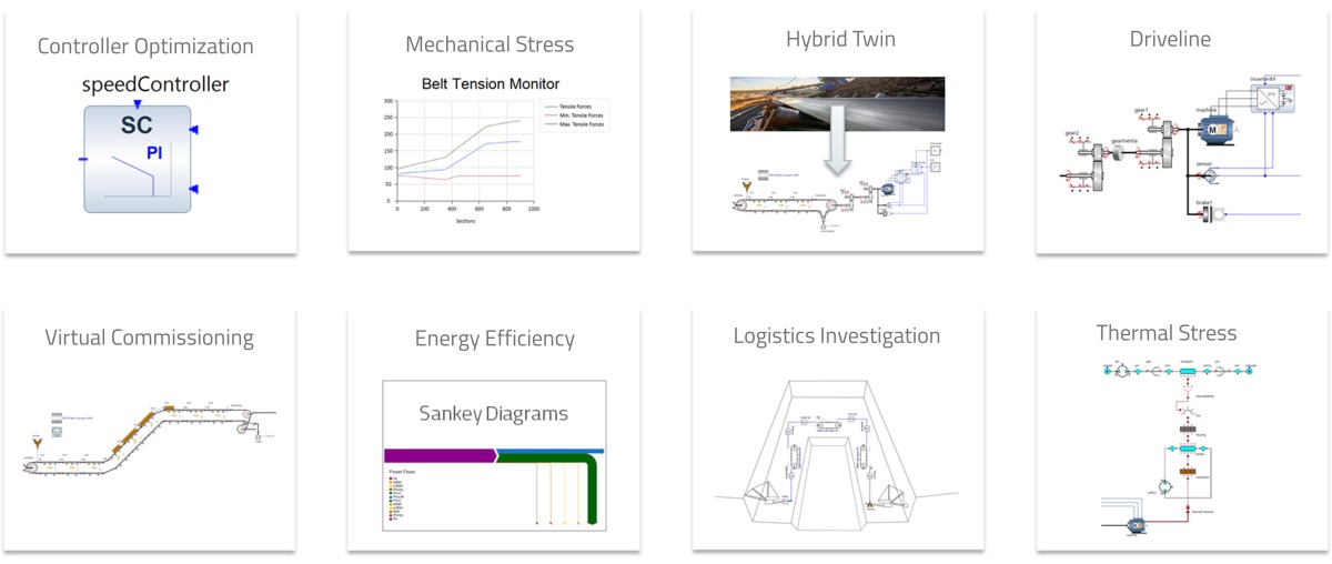
The use of a belt conveyor system model for various calculation and analysis tasks is described below. SimulationX provides the user with support in many diverse applications (Fig. 7) with respect to
Analytical methods (e.g. in the time or frequency range)
Optimisation tasks
Export of code for real-time models and interfaces with real-time platforms and
Co-simulation (integration of external models)
3.1 Vibration analysis of dynamic processes during operation of belt conveyors
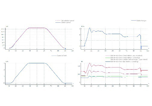
From the initial calculation of dynamic behaviour in [2] up to the present time, one of the fundamental aims of such calculations has been the analysis and evaluation of vibrations in the system. Evaluation of the effective pulling forces and drive torques occurring, and of their effects on the tensioning system, are of prime interest, particularly in special cases and extreme situations.
The bandwidth of the situations examined extends from simple start-up and braking processes, up to and including emergency stops with motor failure, brake application and the jamming of the tensioning weight. An initial utilisation of SimulationX for such investigations is described in [5]. The diagrams contained in Fig. 8 show simulated results for a start-up and braking process (speed, belt velocity, drive torque, effective pulling forces).
3.2 Simulation of the drive train
The model of a belt conveyor can be used as the basis for modelling of detailed drive trains and for vibration analyses concerning the components between the drive pulley and the motor. The necessary component elements, such as flexible couplings, fluid couplings and shafts, and also more extensive gearing models (sprocket stages, bevel-gear stages) are available for this purpose.
This makes it possible to determine, particularly for start-up processes, critical natural frequencies and to analyse and minimise their effects at passage through them during acceleration. Analyses of the drive train using SimulationX models have already been described in [5] and [7]. The gearing structure illustrated in Fig. 9 now also takes into account toothing-properties, including play and fluctuations in system stiffness. This permits, for example, the investigation of torsional vibration and noise emissions, and also of the influence of unbalance excitations.
3.3 The MiL procedure for optimisation of control
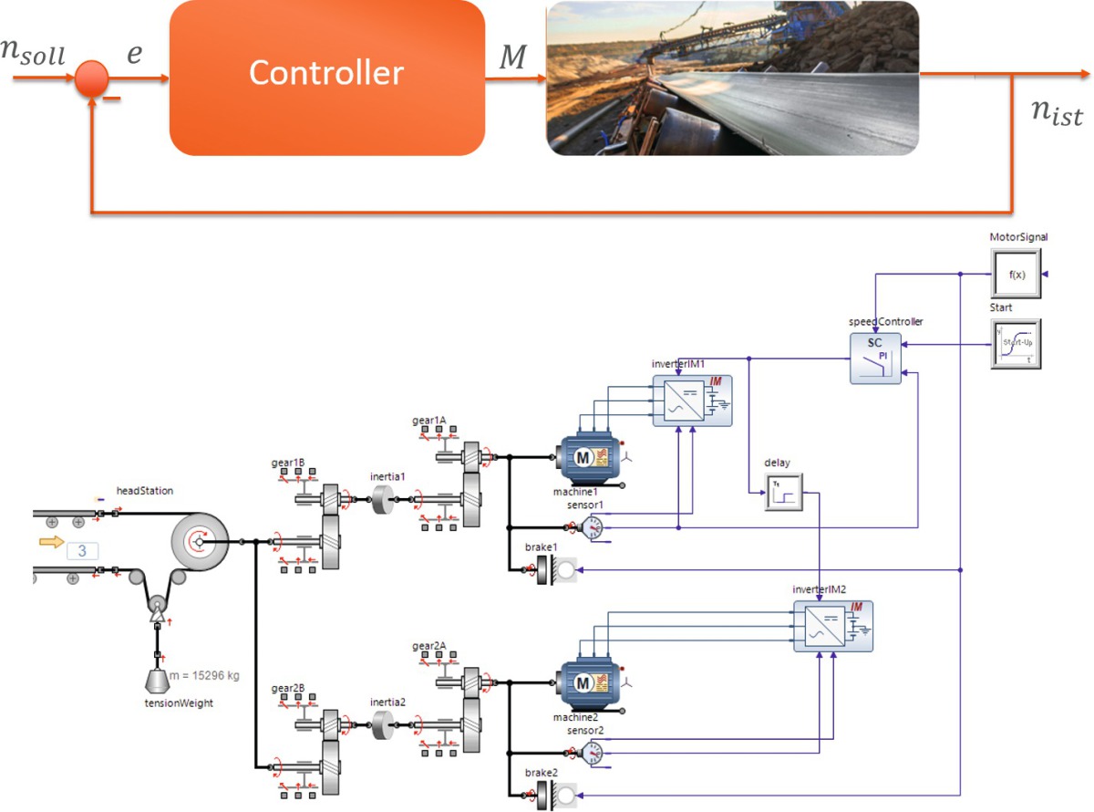
Virtual (pre-)commissioning provides important findings on the anticipated system behaviour of new installations, and of existing systems after modification, such as, for instance, extension of the belt conveyor. Tests and analyses of load-balancing strategies in case of multiple drive pulleys (Fig. 10) can in this way be performed in advance. The “model in the loop” strategies used for this purpose save installation engineers time and costs during on-site commissioning.
The system model can be used for automatic optimisation of control parameters and for efficient and low-risk testing of new control strategies. For this purpose, SimulationX provides – in the form, for example, of the integrated task manager – a facility for automated computations of variants on multiple processor cores and for logging of the results. Automated computation of characteristic load cases (empty/full belt conveyor, start-up under part-load, full ascending/descending, variable load, etc.) assists the user in checking and selecting the control parameters before actual on-site commissioning.
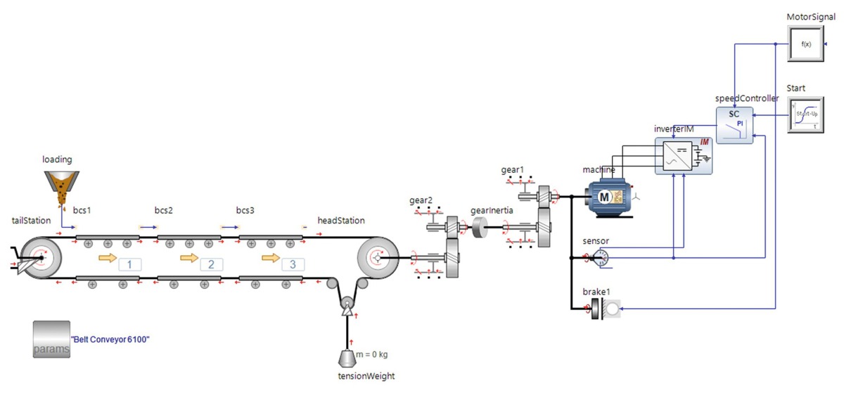
3.4 Analysis of the thermal loading of drive components
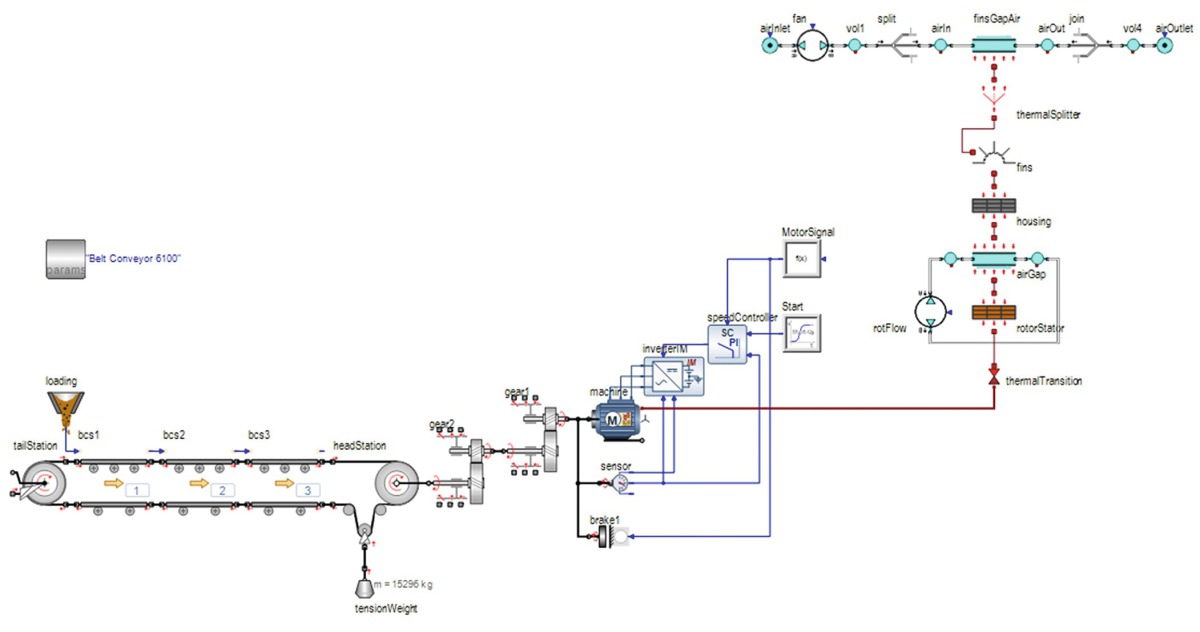
System simulation pursues the philosophy of representing machines and systems component-by-component, combining differing physical domains and taking account of the interactions between the domains. In terms of belt conveyors, a further application is supported in this way. The example shown in Fig. 11 augments the belt conveyor model with a detailed electromechanical model of the motor, inc. power electronics. One of the parameters for the motor model used in this application is the power loss occurring as a function of simulated load spectrum. The power loss (red connection on the motor) is the input variable for a thermal motor model consisting of the rotor, stator, air-gap, enclosure with cooling fins and a fan. This makes it possible to determine heating-up of the motor as a function of ambient temperature, fan characteristics and the belt conveyor’s load cycle. Other components, such as gearing systems and couplings, can also be examined in this way for their thermal behaviour.
4 The Hybrid Twin of belt conveyors
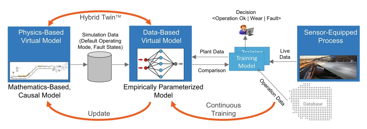
The usability of extensive measured data from system operation, new machine-learning technologies and also cloud applications nowadays permit the generation of digital representations of machines and systems. For this purpose, data-based models - based, for example, on artificial neuronal networks (ANN) - are typically trained and operated in parallel to the actual system. The ESI Hybrid Twin concept consists of the coupling of measured data and data-based models with virtual prototypes (physical models) of the system. Fig. 12 shows the concept behind this idea in schematic form.
The “machine-learning” technologies require one thing, above all: measured data from the system. In the case of new systems, and following optimisations/modifications of existing systems, such data is often not available, or is not available for all operating cases. In this context, dependable physical models can, by means of simulations, provide a basic data set, compute fault states, and thus “teach” the data-based models.
The basic model for the belt conveyor is already available, if models have been created during the design phase and commissioning. Variant computation now makes it possible to simulate various operating situations and use them for data generation. As soon as measured data is available after completion of commissioning, model accuracy can be further increased, and the data-base improved, by means of identification of parameters. Fig. 13 shows such a workflow for belt conveyors. The following sections examine various example applications for the Hybrid Twin concept.
4.1 Identification of model parameters and
controller optimisation during the commissioning phase
The two functions of
parameter identification of model parameters and
optimisation of control parameters
can be effected on an automated basis by means of mathematical optimisation algorithms. SimulationX provides the necessary interfaces with external tools (e.g. Scilab®) for this purpose.
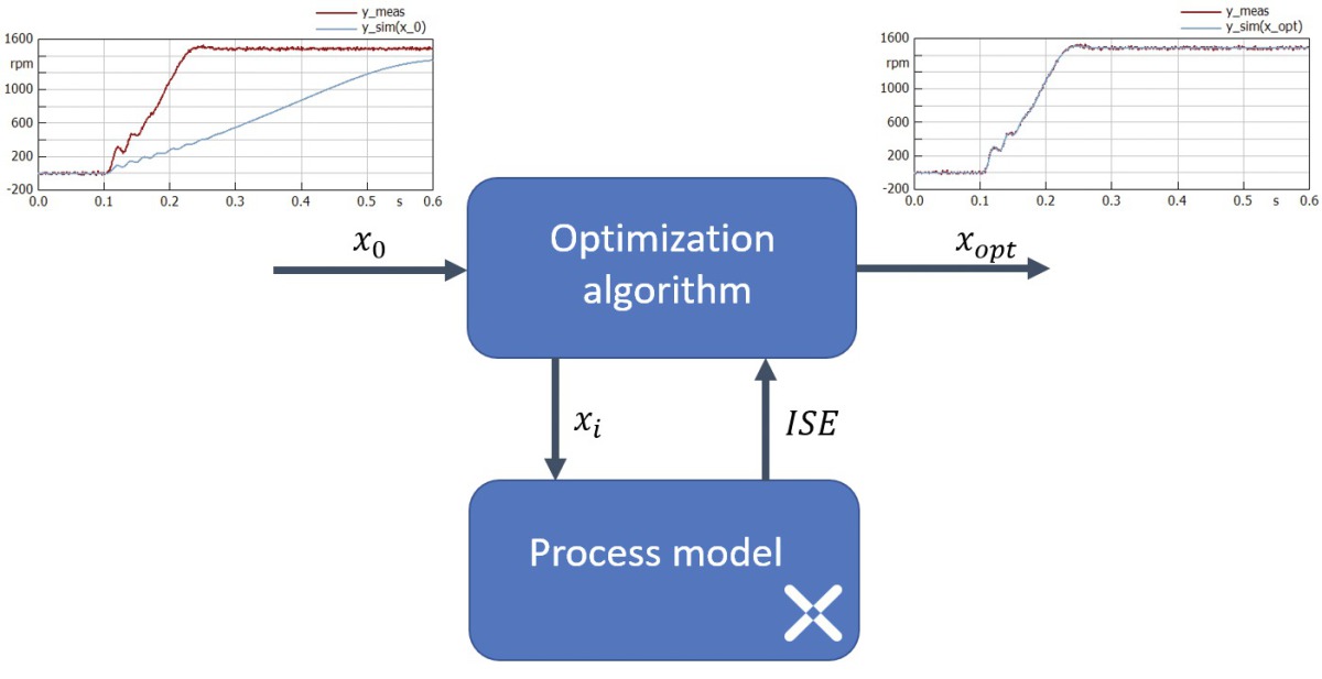
Fig. 14 shows in schematic form an optimisation procedure. A test run in the model is computed on the basis of Starting Parameter Set x0. In the case of parameter identification, measured-data from various operating situations is used while, in the case of controller optimisation, a defined operating scenario involving the specified “desired” behaviour of the control loop is applied. Parameter Set x contains the parameters for the model to be identified respectively the controller parameters to be optimised. A quality criterion, on the basis of which a new Parameter Set xi is determined for the optimisation procedure, is computed at the end of every simulation. Such a quality criterion may, for example, be the “ISE” (integrated square error), the summed squared error between measured (ymeas(t)) and simulated (ysim(t)) signal plot respectively between the simulated and the desired control behaviour.
ISE = ∫ (ymeas (t) – ysim (t))2 dt
The ultimate result is the optimised Parameter Vector xopt. The experienced engineer evaluates the result achieved and will adjust the quality criterion if necessary. The linking of SimulationX models to optimisation tools in this way contributes to further boosting of the efficiency of commissioning engineers.
Using the measured data from load cases operated during commissioning of belt conveyors, the colleagues back in the office identify the parameters of the model and generate a digital twin for representation of the current system state. The thus enhanced model accuracy also permits reliable statements concerning special load cases which cannot be operated and tested during commissioning.
4.2 Representation of current system state
for EnPI optimisation
In accordance with ISO 50001 and ISO 50006, the energy performance index (EnPI) is an important factor in the energy evaluation of a system [8]. The evaluation and plausibility-checking of provisions for improvement of EnPI is an essential element in the certification/re-certification of energy management systems. Corresponding provisions can be reliably investigated and assessed on validated belt conveyor models before actual implementation occurs. Here, it is important to use accurate models which reflect the current actual state of the belt conveyor. This can be accomplished extremely efficiently using the workflow described in Section 4.1.
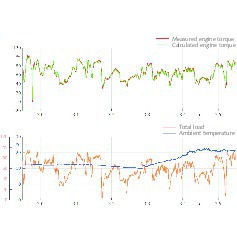
Fig. 15 shows the result of such a model validation. The operating data recorded across several weeks was used for this purpose. A more complex data-preparation process (plausibility checking, excision of non-usable situations [e.g. shutdowns], importation of data) may be necessary, depending on the form in which the data is available. The diagrams show, from top to bottom, the measured and simulated torque of the motors, ambient temperature and the current belt load. The simulation results achieved accord extremely well with the measured operating data.
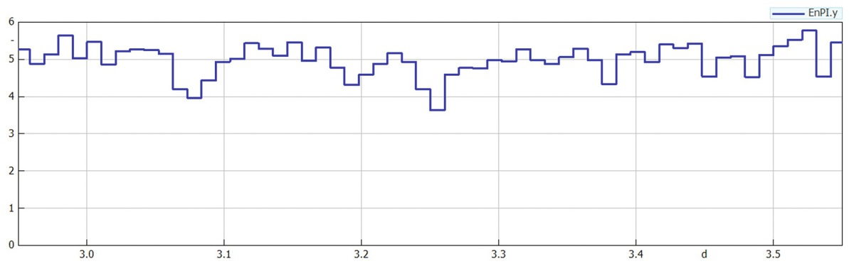
The example plot of EnPI shown in Fig. 16 is calculated from the mass conveyed and the energy required for this on a 15-minute cycle. The length of the evaluation cycle can be varied, depending on requirements. Concepts for EnPI optimisation can now be designed, tested and analysed using this model. Operating strategies involving motor shut-downs at low loads are, for example, conceivable.
4.3 Artificial neuronal networks for on-line determination
of effective tensile forces throughout the system
The Hybrid Twin concept makes it possible to use data from physical models for teaching of data-based models, and thus to create on-line-capable virtual sensors. These permit obtainment of information on the system which would otherwise be obtainable only with great effort, if at all.
The following example illustrates the generation of an artificial neuronal network (ANN) for the determination of effective pulling forces at any selectable point on the belt conveyor. The workflow in this case is as follows:
Generation of a physical belt conveyor model and validation using measured data
Computation and recording of effective pulling forces on the physical model
Design and training of the ANN
Operation of the ANN using measured data for calculation of effective pulling forces
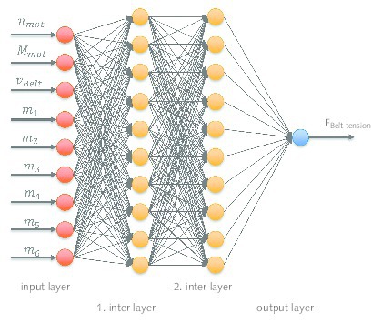
Use is made below of the validated model from Section 4.2 above. The ANN used is a forward orientated ANN with two intermediate layers and ten neurones per layer. Fig. 17 shows the structure of the ANN. Of the nine input variables (e.g. drive torque and speed), the effective pulling force accumulating at the head station is calculated.
Fig. 18 shows the result of the trained ANN. It is thus possible to determine the effective pulling forces on-line and at any belt positions. This additional, virtual, measured variable can be used for monitoring of overloading and of relaxation of the belt.
5 Resumé
This article describes the user-orientated use of system simulation for belt conveyors. It examines selected analysis potentials and applications of a conveyor model for various target specifications and disciplines. The model library discussed can be easily expanded by the user, and is also being continuously further developed by ESI ITI. The use of further computation specifications, country-typical standards and the user’s own concepts is supported. Inclusion of CEMA [4] is to be integrated in the near future, making it possible to select between DIN 22101 and CEMA, depending on the particular target market. Pipe conveyors are a further future expansion stage for the SimulationX belt conveyor library.